Instance textures based on point cloud.
For one of my personal projects, I was in need of generating a large scale terrain (approximately 1500km2 with point density of 16.67 points/m2; more on this in another post). I wanted to experiment with a more flexible and procedural method to texture this terrain and began exploring the texture instancing approach. This allowed me to apply local/spatial overrides to textures based on proximity to different geometry in the scene.
Keeping in mind the large scale of the terrain and having a strong aversion to anything manual, I decided to implement Texture Bombing technology using Houdini’s VEX (Vector Expressions) language. The idea was simple, apply a basic procedural shader to the terrain as a base layer and use texture bombing for spatially localised texture overrides. This would allow me to layer visual complexity dynamically. For the rest of the post, I will refer to texture bombing as texture instancing as it makes more sense to me than the original term (albeit instancing technically means something different…but so does bombing).
Texture instancing is a technique which is fairly similar to geometry instancing in principle. The idea is to read specific textures on disk at specific position and project it on specified input geometry. This is achieved by writing the texture data(filepaths, colour tint etc) onto a point cloud which which also determines the position where the texture is projected onto the specified geometry.
For the implementation, I wanted to stress on certain factors in the specification of the toolset, some of those were as follows.
To accomplish this, I wrote the core technology suite in CVEX which is then used to create shaders and visualisers. This helped in reducing code rendundancy as both SOP tools and shader tools use the same code. It also enforces visual parity between the SOP visualizations and the shaders used for Karma/Mantra renders.
The tool is very generic, to the point that it can be thought of purely as a number cruncher. It performs following steps and outputs the specified data.
This can be performed for any kind of data stored in texture maps (colour, displacements, normals, roughness etc).
Some of the common use cases for Texture Instancing are:
Lets have a quick look at a quick technical demonstration of the process and see what the inputs and output might look like.
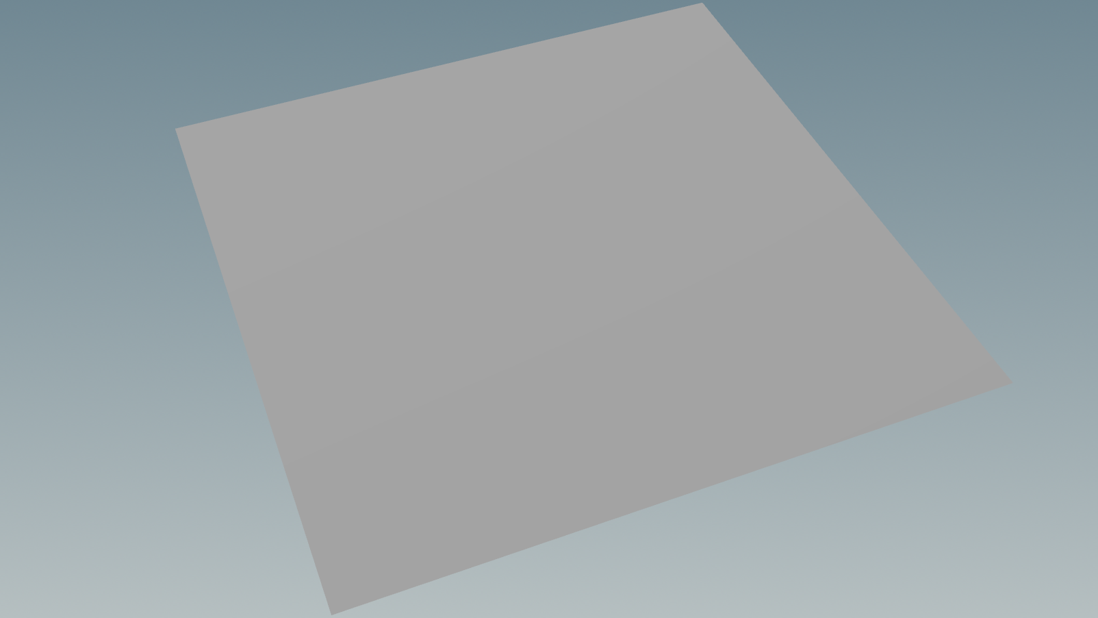
Following is a very simple polygonal grid mesh. We will be instancing our textures onto this grid.
Note: The grid does not have UVs.
Following image shows an example point cloud. Each point of this point cloud, will store the filepath of the texture on disk, position and orientation of the texture projection, scale of the sample texture which will be projected onto the geometry etc.
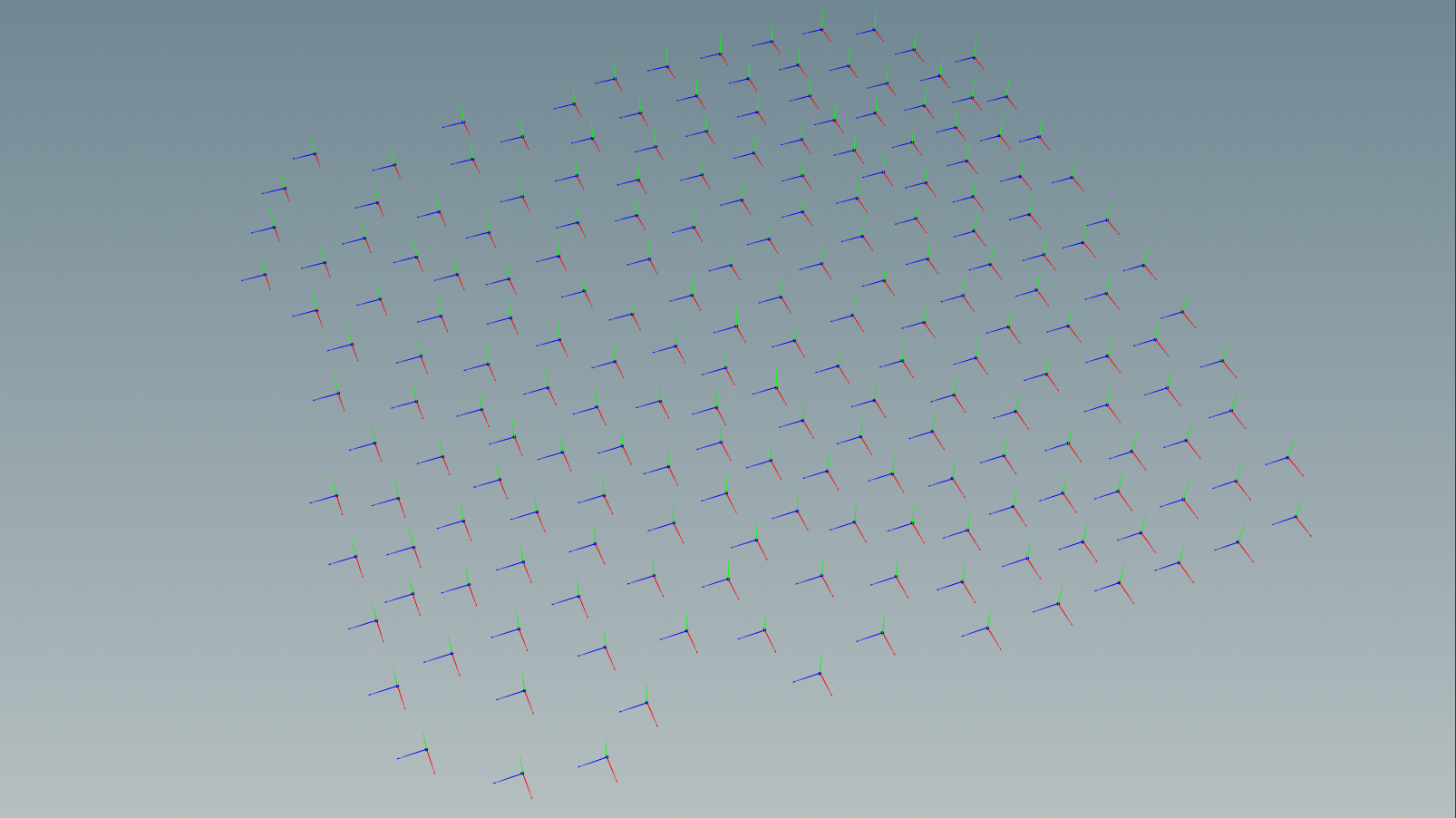
This particular point cloud has following attributes.
For this technical demo, we will be using following texture for all the points. It will allow us to assert whether the orientation of the projections is being correctly enforced or not.
Note: The image alpha is used to cutout the texture and only project the arrow onto the mesh.
Following image shows the output generated by texture instancing process. The texture is applied on the geometry using Tri-Planar projection. Standard instancing behaviour is emulated while computing the projections, meaning the texture will be facing the Z axis defined by the orienation attribute (similar to copying geometry on points using an orient attribute).
The contribution of each point is computed using a inverse distance weighting ie. contribution of each point is directly proportional to the proximity from the point being sampled on the mesh. The farther the point is the lower its contribution will be and conversely the closer a point is the higher its contribution is.
Orientation is visualised as 3 axes (XYZ) at each point position.
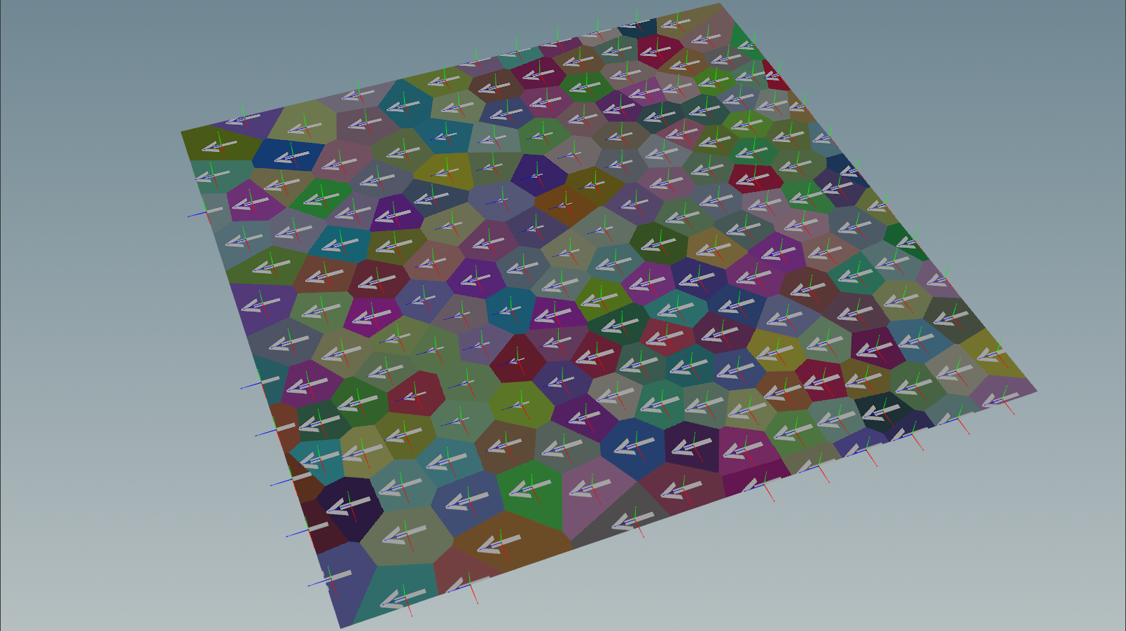
In this test, we only look up a single point to determine texture which means, we will have a clear distinction between each point’s region of contribution (visualised as different colors on the grid).
In contrast to the above example, we now add noise to the orientation. The arrow head correctly orients itself to the specified attribute controlling the orientation.

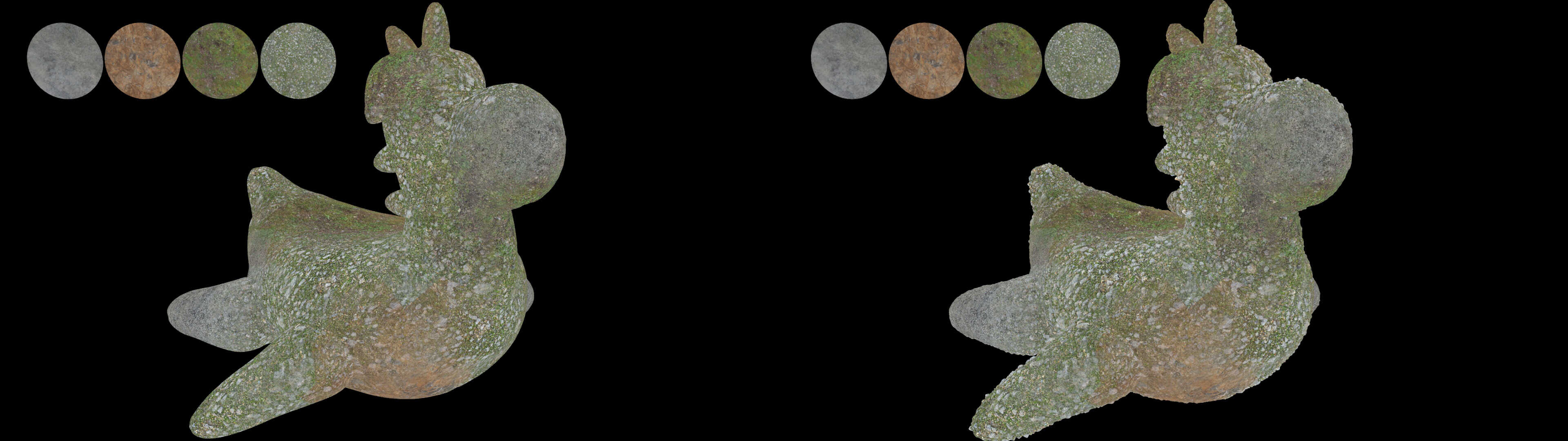
Now lets try this on geometry slightly more exciting than a planar grid. In the following example, we use texture instancing to compute the colour contribution of 4 different textures applied to the input geometry (note that the geometry has no UVs). The 4 different textures are visualized on the top left side of the video.
Another, key point to keep in mind is that there are no UVs on the mesh. The algorithm uses Tri-Planar projection algorithm to generate an implicit UV map which is used for sampling textures.
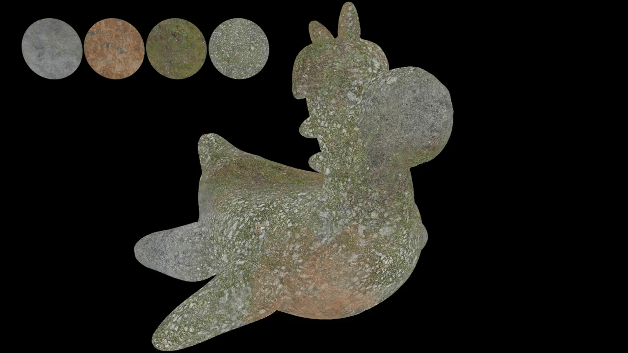
As we are now looking up more than one point, the colour contribution of each point is computed and result is set as the new colour on the mesh. Note the blending that happens between different textures is handled using inverse distance weighting, meaning, for each point in the mesh, closest found point in the point cloud will have maximum influence.
Extending this further, we will also hook in our displacement maps specific to each of the 4 colour maps to compute the displacement at each point of the mesh. In the following example we use texture instancing to compute displacement along with colour using 4 different textures. All the other parameters (scale, orientation, blending exponent etc) are same as previous example.
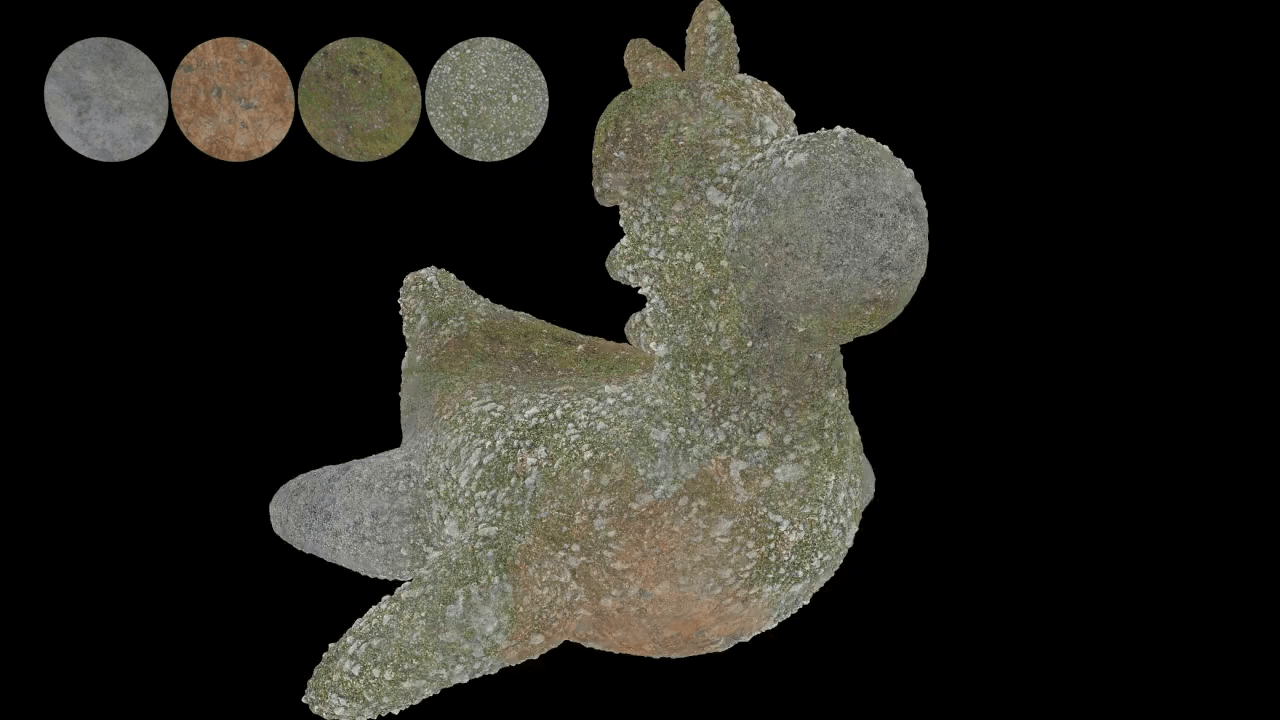
If you look closely in the above example, you will see that the silhouette is being broken by displacements which are computed using the various displacement maps as defined by the point cloud.
Its important to note that each technique comes with its own advantages and disadvantages. Texture instancing in itself is not a magic bullet solution for all your procedural texturing needs! Its a tool with specific set of strengths.
However, it also comes with its own weaknesses.
For the second development sprint, there are few more features I would like to add.
One of the things I want to implement next is depth based blending which is quite standard in game engines such as Unreal Engine. An example of this can be seen in this article.
Additionally, considering large landscapes are quite a common use case for this, I would like to add a planar mode for computing UV space to speed up the computations.
Expose few texture sampling filters (box, gaussian, blackman, sinc etc) as parameters for users.